Jump to content

Recommended Posts

Posted (edited)

Our marina in Point Breeze is swamped with work orders and I just needed to have a couple issues fixed on my little 9.9 Yammer 4 stroke. No water was coming from the pee hole and after checking it for wasp nests and spiders, pulled the stick for oil and oil gushed out!.. it was way overfull! Making oil is never good since it dilutes the sump oil and can wipe bearings pretty quickly. I can't wait for it to get fixed, so I took matters into my own hands and ordered parts from boats.net. I have made orders from them before and they are top notch in ease of part identification and part stock and over nite express shipping. Genuine manufacturer marine parts for most common motors, cowl to skeg.

So after examination of the parts diagram related to my outboard, I ordered a couple diaphragm parts for the mechanical fuel pump to stop the gas going in the oil of the 4 stroke. Then ordered a complete water pump repair kit to get the water to the power head.

post-140268-14343835557258_thumb.jpg

I made a pictorial on the water pump job and for anyone who has a small amount of mechanical skills, it can be done very easily on this motor. My 9.9 model is a 2004 MLHC four stroke. So here is what you need for tools, supplies and time.

Tool list is small.

Stool to sit yer butt on! Shade, beers..time depends on how many beers..about an hour...maybe two... with more beers:unsure:

Pliers

One 12mm combination wrench or socket and ratchet.

Two 10mm open end wrenches

#2 Phillips screwdriver

Medium Flat blade screwdriver

Plastic hammer mallet.. brass will work too

Supplies are water hose and jet stream spray nozzle, brake cleaner with the straw sprayer, rags, some type of lube for the impeller, petroleum jelly, oil, no solvents! ..I used some synthetic 75w 90 gear oil I had left from axle work.

Here we go! First have your engine at a comfortable height.mine was on it's bracket and just right when I dollied the trailer up or down.

Next get your stool and place it on the side of the motor leg with the engine tilted up. Then put your motor gear in reverse and look down the leg in front and find the space where your shift rod is visible. If you are in reverse gear there will be a connection you can see and will take apart with the two 10mm open wreches. Small nut is the locker of the larger brass nut which you turn the brass nut clockwise to disconnect the rod. Spin it only enough to disconnect...leave the lock nut backed off on the lower rod.

post-140268-14343836943306_thumb.jpg

Next get your 12mm wrench or socket and remove the 4 bolts holding the gear case to the leg. Hang onto it! It will slide right off. What you will have is the gear case and prop intact and the drive shaft and lower shift rod on the top side. That was easy!

The water pump is on top of the gear case assembly with the drive shaft going into it and passing on into the gear case below. Don't worry, no disassembly of the gear case is necessary with this repair.

Four bolts and two retainers are removed next from the top of the pump assembly, you need the 10mm wrench for that.

Slide the top housing up off the drive shaft, it contains the impeller cup you will replace with new one in the kit.

post-140268-14343838842473_thumb.jpg

post-140268-14343845838721_thumb.jpg

Then slide the impeller up off the shaft with the help of a screw driver if you need to break it free and use some oil on the shaft for help sliding it off.

post-140268-14343848559107_thumb.jpg

Now remove the half moon key from its slot in the shaft that pins the impeller in place.

post-140268-14343850976112_thumb.jpg

The rest of the parts slide off the shaft the same way. Wear plate, two gaskets and that is it for the pump. Everything else stays intact.

post-140268-14343851723552_thumb.jpg

post-140268-14343852863068_thumb.jpg

Use the jet spray from the water hose and flush out any rubber pieces from the lower case seal area. Inspect it closely for any pieces lodged in the crevice of the seal and peck them out CAREFULLY! don't damage the seal!

post-140268-14343856249848_thumb.jpg

Brake cleaner can be used to clean the shaft so it is smooth and ready for reassemble.post-140268-14343856939775_thumb.jpg

The water pump housing (plastic) has the metal cup lightly pressed into its cavity. Remove the two phillips screws on the opposit side, remove that part of the housing and pry out the rubber grommet. Then I used the flat screwdriver to remove the metal cup by coming through the opposite side and just catching the edge of the old cup with the blade while being sure not to rest the blade on the plastic housing, placed the handle of the screwdriver a hard surface and used the plastic hammer to strike the housing enough to dislodge it so I could grab the cup edge with pliers and remove it.

post-140268-14343857904049_thumb.jpg

post-140268-1434385875795_thumb.jpg

Notice the tang and slot that mate together when reassemble of new cup in its cavity. Clean the cavity out and remove all pieces of rubber then lightly lube the inside of the cavity. Tap the new cup into place with the plastic hammer, being sure to align the tab into the slot in the cavity.The edge is nearly flush with the housing when fully seated. On the opposite side is the rubber grommet cavity you install the new grommet.

post-140268-14343860173571_thumb.jpg

post-140268-14343860533093_thumb.jpg

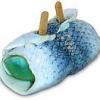
It has a tapper on the inside diameter and doesn't matter which way it goes in. It is the seal for the water tube still up in the leg. It has a pointed end to help it align with the grommet when putting the lower unit back into the leg.post-140268-14343838221214_thumb.jpg

Brass colored water tube in the leg

Clean all the mating surfaces that have gasket seals, flush the water tubes goin down into the pickup screen above the gear case with the jet spray nozzel, and now assemble the parts in order that came off of the shaft.

post-140268-14343861479845_thumb.jpg

The grommet side of the pump housing goes towards the prop side as well as the wear plate and gaskets. It can go on backwards and you will not be able to put it into the leg to align with the water tube. In order here you go!

post-140268-14343862064362_thumb.jpg

Gasket

post-140268-14343862380933_thumb.jpg

Wear plate

post-140268-14343863016384_thumb.jpg

Gasket

post-140268-14343863251074_thumb.jpg

Half-moon key in the shaft slot

post-140268-14343863760359_thumb.jpg

post-140268-1434386910087_thumb.jpg

Impeller next...KEY SLOT DOWN! lube the shaft so it slides easy and fit slot onto the key resting solidly to the wear plate.

Then the assembled housing down the shaft and with a gentle twisting pessure action and some light lube, work the vanes of the impeller into the metal cup.

Install the 4 new cap screws in the housing along with retainers and tighten cross pattern evenly. Be gentle it's plastic housing! That's it! Now the leg assembly comes next.

Slide it back up in the leg while keeping the unit aligned evenly and "feel" the shaft into the power head. You can turn the prop back and forth to mesh the splines and the water tube should guide into the top of the water pump housing grommet as it seats up against the lower leg. Lightly install the four bolts holding the lower unit to the leg. Find that shift rod you took apart and connect them back together. Screw the brass connection nut back down to its original location and your gear shift lever should be close to adjustments. Then tighten the jam nut to it using two open end 10mm wrenches. Tighten the lower unit 12mm bolts evenly in cross pattern. I'm sure there is a torque spec but I don't know what it is. Just be sure not to over tighten because you are dealing with aluminum.. test it in water tub and never run the engine without water! Make sure your shift lever will engage forward, neutral and reverse. If not, adjust the brass nut on the rod and retighten the jam nut to hold it.

post-140268-14343870019156_thumb.jpg

All the junk and all the new!

Hope this helps someone with a similar engine do the job themselves!:lol::D

Mark

Sent on a Sprint Samsung Galaxy Note® 3

post-140268-14343833004808_thumb.jpg

post-140268-14343833590159_thumb.jpg

post-140268-14343834684585_thumb.jpg

post-140268-14343858792206_thumb.jpg

post-140268-14343868926541_thumb.jpg

Edited by skipper19
Posted (edited)

post-140268-14343886517431_thumb.jpgpost-140268-14343886839908_thumb.jpg

This diagram is from the boats.net site and has very detailed description of all parts of any systems in your model of engine.

This particular diagram is for the fuel pump on my 9.9 mlhc and I replaced the diaphragms in the pump.

The second picture is the kit part number for the water pump kit. This has been the best site for ordering do it yourself parts I have found. My OX66 225 YAMAHA has also been supplied parts by them for me to maintain the fuel injection system as well! Great site!

boats.net

Mark

Edited by skipper19
Posted

Good nob. Nicely detailed. This will definitely help guys out. Same process for almost all outboards u der 25 hp. Good job

Sent from my SCH-I545 using Lake Ontario United mobile app

Create an account or sign in to comment

You need to be a member in order to leave a comment

Create an account

Sign up for a new account in our community. It's easy!

Register a new account

Sign in

Already have an account? Sign in here.

Sign In Now
×
×
  • Create New...